Warning: Undefined array key "HTTP_REFERER" in /usr/www/users/empower1/amplifier-notes/pulse-shaping.php on line 63
>
Back
Pulse shaping, as it is done today, is an effort to fix fidelity issues caused by the transmitting amplifier and is accomplished by a combination of imperfect methods, most external to the amplifier. In this industry briefing George Bollendorf explains a new approach that matches input pulse signal shape, minimizes droop, overshoot, ringing, rise and fall times.
Pulse shaping is a leap ahead technology that we are perfecting for implementation into our existing high power amplifier architecture. This next feature set for our multi-mode interoperable SSPA’s has particular significance for electronic warfare applications. No other amplifier manufacturer in the Western world has this capability and so I thought you would be interested to learn of our progress given its relevance.
Here’s the problem we are solving . . .
High power amplifiers do a poor job duplicating the input signal without distortions. Due to the transient response of the amplifier the output will over shoot, ring and droop, introducing undesired low and high frequency components into other parts of the spectrum.
By using a digital feedback loop within the rf chain, the amplifier issues can be fixed where they occur, within the amplifier, eliminating the need for external pulse processing and with the added benefit of overall system cost. One benefit worth mentioning up front is with EW threat simulation applications where this pulse duplicating ability allows the amplifier to reproduce recorded or live adversary signals with high fidelity.
Although we are calling this approach “pulse shaping” it is a bit of a misnomer. The term “pulse shaping” typically refers to approaches that shape the input pulse to influence the amplifier output shape. Using a pseudo random Gaussian shape for the RF input signal is one such method that slows the rise and fall time of the RF input pulse. The trade off with Gaussian shaping is slow rise and fall times that limit duty cycles. Our proof of concept is a demonstration of the amplifier having calculated the error of the output waveform and storing it in a look up table that is then applied in real time to the input rf. In other words, the amplifier issues are solved within the amplifier, in RF, and not externally by the system designer. With that said this ability would be better described as “pulse shape matching”.
FIG 1: Digital Loop Feedback Engine for Pulse Shape Matching
Highlighted in Figure 1 are the functional blocks for implementing the pulse shape matching function. The technology used is based the composition of a function with its inverse I (Identity function).
In other words we use digital signal processing techniques to take the inverse of the error function and sum it to the input.
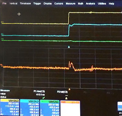
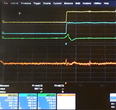
FIG 2
Starting with Figure 2 you can see the demonstration of the problem and the output pulse shape initial conditions. The yellow pulse is the input RF pulse, the amplifier output and its nonlinear response is in Blue. The Orange trace is the error between the Yellow and Blue signal, including the rising edge slope (not to scale). The Green trace is the accumulated applied inverse error.
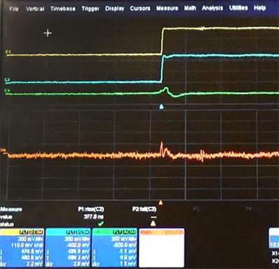
FIG 3
In the Figure 3 screen shot you can see the start of the pulse shape matching function. In this case the error starts out large so as the error is applied, it has to be accumulated to the next error measurement (the Green trace). Equivalently you can see the present state error function is now smaller.
FIG 4
Again, on the next cycle, Figure 4 shows the remaining error applied. The output pulse virtually matches the input. The accumulated applied error is larger (Green) and the present state error is smaller (Orange). The loop runs continually while adjusting for any present conditions in the error function, including droop.
SUMMARIZING,
Digital Pulse Shape Matching Enables Break Through Capabilities for EW and Radar
The amplifier reproduces the recorded threat or “encountered” threat pulse
Droop is minimized – reducing capacitance on VDD
The amplifier compensates for pulse error due to temperature
System Engineers don’t need to do their own pulse shaping
Each individual amplifier no longer needs “unique” calibration
Simplify systems integration complexity and cost
Empower RF Systems manufactures the most advanced high power system amplifiers in the world with solutions for defense, commercial, and industrial applications. Our products incorporate the latest semiconductor and power combining technologies and originate from an extensive library of "building block" designs. Solutions range from basic PA modules to multifunction PA assemblies with real time embedded microprocessor control, programmable detectors, and re-configurable digital loop control.